If you’re experienced with cameras, you know that you need a minimum amount of distance between yourself and the object you’re trying to photograph. No matter how sharp the resolution of the camera, you can only get so close before it starts to lose focus. Exactly how close depends on the camera, but there’s a limit to how much an ordinary lens can bend the light before it becomes too distorted to show fine detail.
As an experiment, try holding your smartphone camera a quarter inch away from a book, and chances are you’ll get something that looks like the image at right. Now try holding it even closer, until the lens is right up against the paper. That’s the job that a check scanner – or an ordinary flatbed scanner, for that matter – has to do.
Fortunately for us, modern check scanners don’t use regular cameras, but rather a specialized type of industrial sensor called a contact image sensor, or CIS. (See our related article, Why the “camera” in your scanner isn’t really a camera at all.) These are purpose-built devices made to take pictures from extremely close up at a fixed distance, at the expense of … well, just about everything else.
What’s in a CIS, and what came before it?
In a nutshell, a contact image sensor is a line of photosensors representing one pixel each (more accurately, a zig-zagging double line of partially overlapping photosensors, but the result is the same). Each one of these photosensors has a tiny, rod-shaped lens of fiberoptic material directly in front of it. The rods are “dumb” fixed lenses that simply focus light straight ahead from a predetermined distance, and don’t have any ability to move or make adjustments. So, the CIS is very good at one specific function, which is taking a picture of paper that’s pressed right up against the glass.
The entire mechanism – sensors, lenses, glass, and light source – is contained in a pre-assembled enclosure that is easily mounted inside a larger scanning device. The CIS is readily mass-produced and relatively inexpensive, making it truly ideal for this type of work.
But contact image sensors have only been around since the 1990s, and they didn’t really make it into use in check scanners until the early 2000s. Banks had already been capturing images of checks for decades before that, but those devices had to rely on older technology that worked much more like a regular camera.
The type of sensor used in early check scanners, and in reader/sorter machines before them, was the charge-coupled device, or CCD. That acronym may be familiar to photography buffs or electrical engineers because it is the same type of sensor that was used in early digital cameras. In fact, CCDs are still used today in specialized devices that require the highest resolutions and finest sensitivity; they’ve just been beaten out by other things on price and simplicity for mass-produced electronics.
Scanner CCDs – the same as a camera, and not the same
As explained in this article about digital microfilm conversion by our nextScan microfilm division, scanners and “regular” cameras capture light in different ways. A traditional point-and-shoot camera uses an area array sensor, or in other words, a 2D sensor that takes one still shot of a scene or object all at once. Scanners use line scan technology, which means they have a 1D sensor – a single line of photosensors that captures one-pixel “slices” in rapid succession, where either the camera or the subject of the image needs to be moving.
To make a long story short, the CCDs in early scanners were 1D line-scan arrays, just like the CIS in a modern scanner, and they captured the check images in tiny slices, just as the CIS does today. Unlike a CIS, though, these CCD arrays didn’t have the benefit of the fiberoptic rods to aid with short-distance focus. They had to rely on a regular lens, just like a regular camera – and that meant the sensors had to be set back a sufficient distance for the light to focus. In the case of check capture, that was about eight to ten inches.
Bending the rules
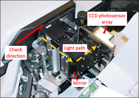 If you’ve seen a check scanner before, you know that there isn’t really any room for a camera that’s 10 inches long. So, our engineers had to cheat a little, and they used mirrors to extend the focal length in a different direction.
In full-sized reader/sorter machines, like the old Burroughs NDP, we could get away with using a single mirror. This changed the direction of the light so that it was traveling parallel to the paper track, down the length of the device rather than having a camera sticking out of it sideways. Since a reader/sorter could be 20 feet long (or even longer), that gave us plenty of room to work with.
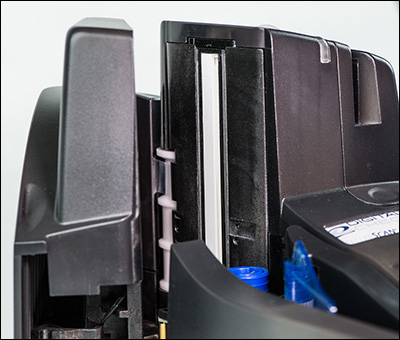
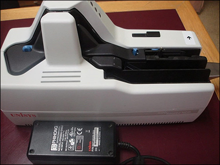
As scanners got smaller, though, that technique wasn’t going to cut it. In a desktop scanner, space is at a premium, and yet the CCD array still required the same eight to ten inches. So, we had to turn the light back on itself using multiple mirrors. Our earliest scanner that could truly be called a “desktop” model, the Source NDP, used two mirrors to reflect the light in a Z-shaped path, which ended at a CCD photosensor that was underneath the paper track near the base of the device.
Naturally, this type of optics required a great amount of precision, similar to a telescope or a microscope set to look at an exact distance. So, the entire camera assembly was a single factory-sealed unit that was designed not be adjusted or disassembled for the lifetime of the device.
Given the permanent nature of the camera assembly, it was extremely important to keep dust and debris out, since the internal components couldn’t be cleaned except at the factory. That required very tight metalwork with finely machined parts, fastened by multiple screws, and sealed at the joints with an adhesive.
Needless to say, this was all very intricate work that was not well suited for mass production, and so the CCD cameras alone on these old devices could cost as much as a whole scanner does today. While they were impressive feats of engineering, as soon as practical CIS assemblies became available, making the switch was an easy choice.
Lighting the way
 An often-overlooked, but still critically important part of the image capture process is how to light up the documents inside the paper track. When you’re scanning documents, no natural light gets inside the machine, so you have to provide your own.
With a modern CIS assembly, that’s relatively simple. The sensors get sufficient illumination from small LED light sources sitting right next to them in the assembly, and that’s all there is to it.
Of course, 30 or more years ago, there were other challenges, one of which was that compact, inexpensive LED lights as we know them simply weren’t available. And if that wasn’t enough, CCD arrays needed about 10 times more light than a modern CIS or CMOS sensor to capture a quality image.
That meant we had to provide some serious illumination – and not only that, but distribute it evenly from top to bottom across the document as it moved past. A simple vertical slit wasn’t good enough if the light was coming from a single source, as the center would receive much more illumination than the outer edges.
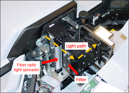
In the highest-speed reader/sorters, such as the 2,000 document-per-minute NDP 2000, the amount of lighting required was extreme. That machine actually used a halogen bulb intended for helicopter landing lights, which typically weighed in at around 600 W . The heat it threw off was so intense that the checks could actually catch on fire if they stopped in front of the camera for too long, and so an automatic shutoff system had to be devised. Smaller devices like the Source NDP could use high-intensity LEDs. To shine the light evenly from top to bottom, it was passed through a bundle of fiberoptic strands that ran vertically in the paper track, fanning out the light from its point source.
Do You See What I See?
 The other issue that early scanners had to contend with was color perception. That is to say, machines don’t “see” light in the same way that Homo sapiens eyes do.
Our own human vision favors the middle of the spectrum, so that greens stand out the most, along with their neighbors blue and yellow. Colors toward the extreme red and violet ends of the spectrum are comparatively toned town. Mechanical sensors, however, absorb light across all wavelengths at basically the same rate.
Of course, checks (and basically all other kinds of documents) are printed in color schemes that look right to our own eyes. So, what looks like a bright green to us might not actually be that bright at all; or what looks like a pale off-white might actually contain a lot more red than we think.

At right, we see a check in normal light in the image on top. In the bottom image, the green has been turned down, and the red and violet have been enhanced, to approximate how that same check might appear to a machine. Take a look at that and you can see why, for example, red gel pens are notorious for causing “disappearing” signatures and dollar amounts in the scanning process.
In order to compensate for the difference between human vision and the “true” light levels in the world at large, early scanners used a filter that produced the reverse effect of what you see in the bottom image – toning down the far ends of the spectrum to compensate for the extra saturation there that’s invisible to us. Modern, CIS-based scanners use three sets of red, green, and blue LEDs to produce the lighting, and simply adjust the intensity of each color to compensate for this issue, instead of using a filter.
We hope you’ve enjoyed this look back at the way we used to work with light and optics back before what you would call “modern” lighting and cameras were commonplace. There’s always a difficult transition phase during the era when analog meets digital, where manufacturers need to invent creative ways to engineer around unforeseen problems. Fortunately, we were up to the task, and we hope it’s given you some insight into the process of constant improvement that led to the scanners you use today!